Getting Started
Ameba ARDUINO: Getting Started with AMB23
Required Environment
AMB23 board currently supports Windows OS 32-bits and 64-bits (WIN7/8/10), Linux OS (Ubuntu 18 LTS/20 LTS/latest) and macOS operating systems. Please use the latest OS version to have the best experiences. In this documentation, please use the latest version Arduino IDE (at least version 1.8.12).
Introduction to AmebaD[AMB23]
Ameba is an easy-to-program platform for developing all kind of IoT applications. AmebaD is equipped with various peripheral interfaces, including WiFi, GPIO INT, I2C, UART, SPI, PWM, ADC. Through these interfaces, AmebaD can connect with electronic components such as LED, switches, manometer, hygrometer, PM2.5 dust sensors, …etc.
The collected data can be uploaded via WiFi and be utilized by applications on smart devices to realize IoT implementation.

AMB23 has smaller size than Arduino Uno, as shown in the above figure.
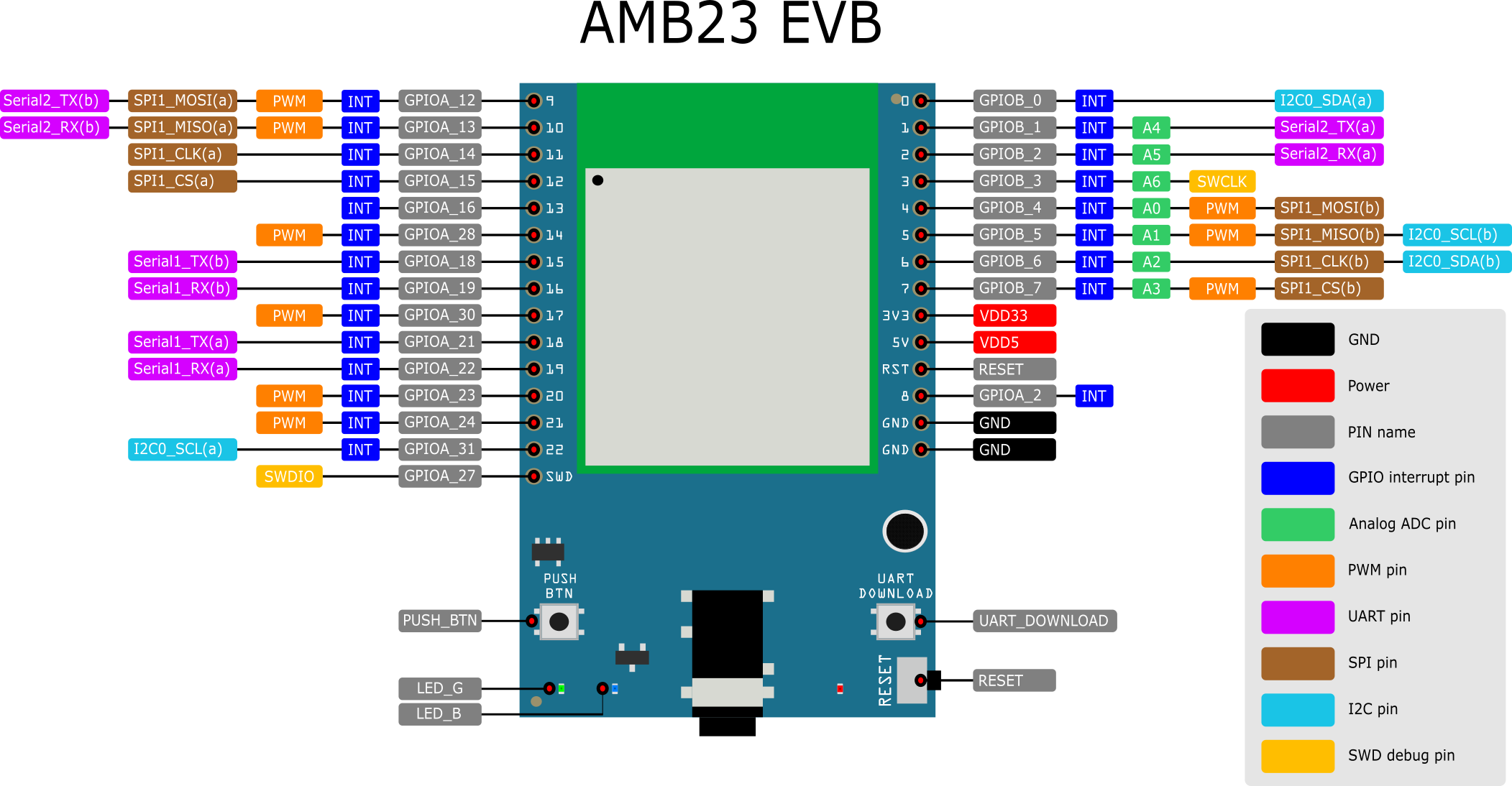
# |
PIN name |
GPIO INT |
ADC |
PWM |
UART |
SPI |
I2C |
|---|---|---|---|---|---|---|---|
D0 |
GPIOB_0 |
✓ |
I2C0 SDA |
||||
D1 |
GPIOB_1 |
✓ |
A4 |
Serial2_TX |
|||
D2 |
GPIOB_2 |
✓ |
A5 |
Serial2_RX |
|||
D3 |
GPIOB_3 |
✓ |
A6 |
||||
D4 |
GPIOB_4 |
✓ |
A0 |
✓ |
|||
D5 |
GPIOB_5 |
✓ |
A1 |
✓ |
I2C0 SCL |
||
D6 |
GPIOB_6 |
✓ |
A2 |
I2C0 SDA |
|||
D7 |
GPIOB_7 |
✓ |
A3 |
✓ |
|||
D8 |
GPIOA_2 |
✓ |
|||||
D9 |
GPIOA_12 |
✓ |
✓ |
Serial2_TX |
SPI1_MOSI |
||
D10 |
GPIOA_13 |
✓ |
✓ |
Serial2_RX |
SPI1_MISO |
||
D11 |
GPIOA_14 |
✓ |
SPI1_CLK |
||||
D12 |
GPIOA_15 |
✓ |
SPI1_CS |
||||
D13 |
GPIOA_16 |
✓ |
|||||
D14 |
GPIOA_28 |
✓ |
✓ |
||||
D15 |
GPIOA_18 |
✓ |
Serial1_TX |
||||
D16 |
GPIOA_19 |
✓ |
Serial1_RX |
||||
D17 |
GPIOA_30 |
✓ |
✓ |
||||
D18 |
GPIOA_21 |
✓ |
Serial1_TX |
||||
D19 |
GPIOA_22 |
✓ |
Serial1_RX |
||||
D20 |
GPIOA_23 |
✓ |
✓ |
||||
D21 |
GPIOA_24 |
✓ |
✓ |
||||
D22 |
GPIOA_31 |
✓ |
I2C0 SCL |
Setting up Development Environment
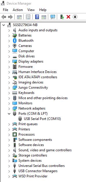
Step 1. Installing the Driver
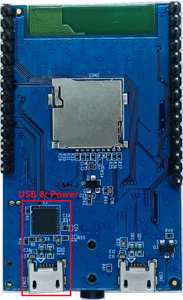
First, connect AMB23 to the computer via Micro USB (same as power):
Step 2. Set up Arduino IDE
And paste the following URL into “Additional Boards Manager URLs” field:
https://github.com/ambiot/ambd_arduino/raw/master/Arduino_package/package_realtek.com_amebad_index.json
Next, go to “Tools” -> “Board” -> “Boards Manager”:

The “Boards Manager” requires about 10~20 seconds to refresh all hardware files (if the network is in bad condition, it may take longer). Every time the new hardware is connected, we need to reopen the Board Manager. So, we close the “Boards Manager”, and then open it again. Find “Realtek AmebaD Boards (32-bits ARM Cortex-M33 @200MHz)” in the list, click “Install”, then the Arduino IDE starts to download required files for AmebaD.

“AmebaD_Arduino_patch1_SDK”, please select at least 1 of the SDKs. There are 5 latest released SDK options.
“AmebaD_Arduino_patch2_Tools”, please select according to your operation system. There are Windows, Linux and MacOS.
“AmebaD_Arduino_Source_Code”, this section is optional download only wants to refer the latest source code.
Download the files selected, then unzip (patch1 and patch2 are compulsory). There are “Install.doc”/“Install.pdf” for you to refer installation steps. According to your system, please run the installation tool in the “Offline_SDK_installation_tool” folder.
After the installation tool running successfully, you may open Arduino IDE and proceed to “Tools” -> “Board“ -> “Boards Manager…”. Try to find “Realtek AmebaD Boards (32-bits ARM Cortex-M33 @200MHz)”` in the list, click “Install”, then the Arduino IDE starts to download required files for AmebaD.
Finally, we select AmebaD as current connected board in “Tools” -> “Board” -> “Ameba ARM (32-bits) Boards” ->” RTL8722DM MINI”:

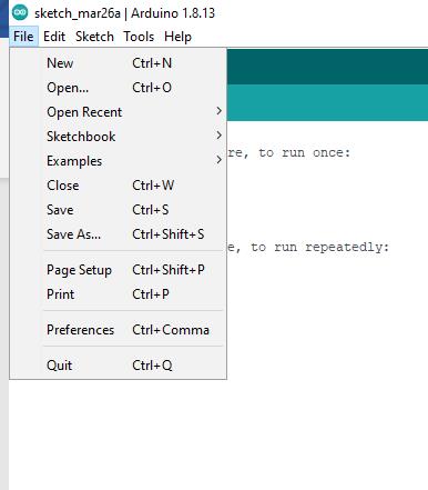
Try the First Example
Step 1. Compile & Upload
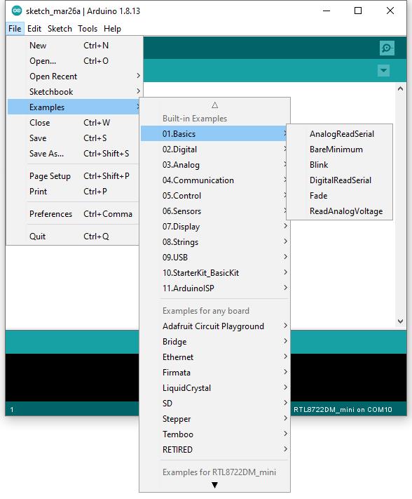
Arduino IDE opens a new window with the complete sample code.

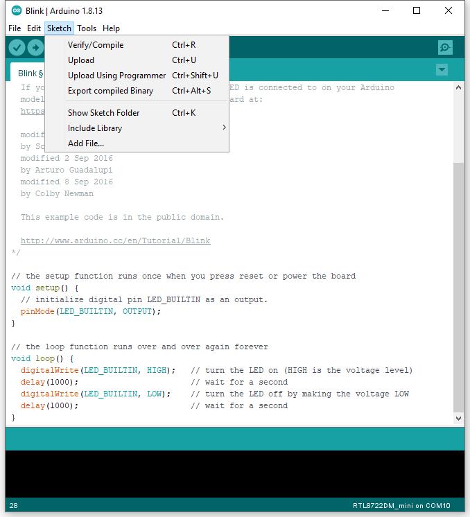
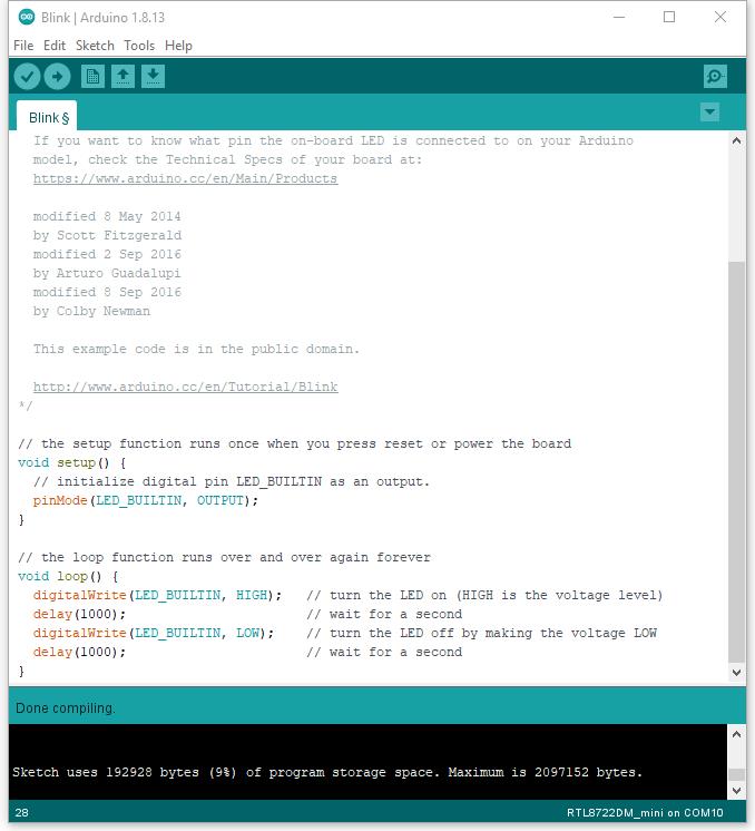
Next, we compile the sample code directly; click “Sketch” -> “Verify/Compile”
Arduino IDE prints the compiling messages in the bottom area of the IDE window. When the compilation is finished, you will get the message similar to the following figure:
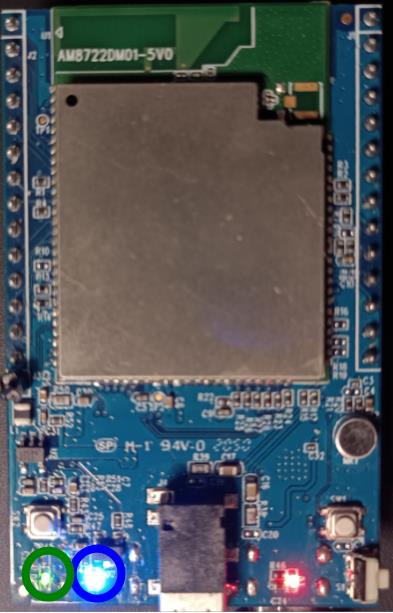
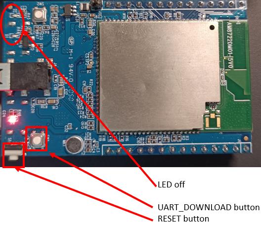
To enter the upload mode, first press and hold the UART_DOWNLOAD button, then press the RESET button. If success, you should see the onboard green LED and blue LED all turned off.
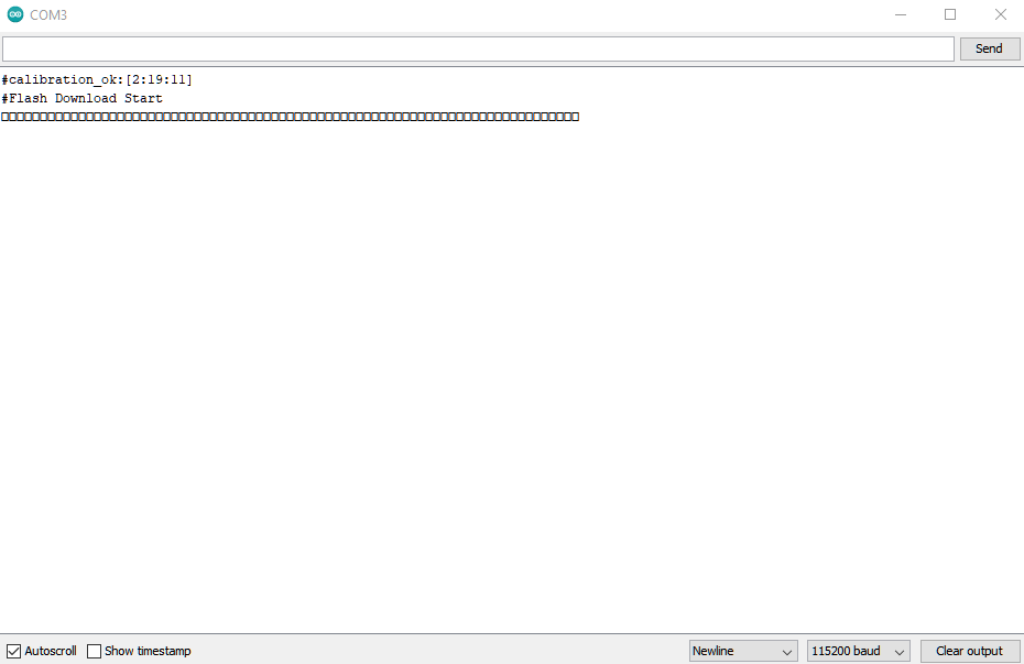
It is optional for users to check if the board entered the upload mode. Open serial monitor/terminal and look for “#Flash Download Start”. Note, it is normal that some serial terminals may show unknown characters as following picture.
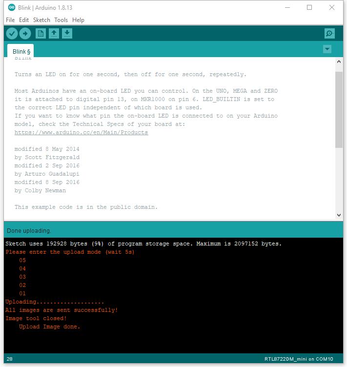
Again, during the uploading procedure the IDE prints messages. Uploading procedure takes considerably longer time (about 30 seconds to 1 minute). When upload completed, the “Done uploading” message is printed.
Step 2.Run the Blink example
(End)
Note
If you face any issue, please refer to the FAQ and Trouble shooting sections on Support page.